Glossary
Technical terms briefly explained
ASA Schalttechnik GmbH
F.-A.-Meyer-Str. 4
32457 Porta Westfalica
Germany

The relevant provisions of the employers' liability insurance associations and the regulations of the TÜV technical inspection associations place high demands on occupational safety. ASA accident protection covers are the right step towards occupational safety and employee protection. They are made of a high-quality cast aluminum alloy and completely shield the foot control pedal upwards and to the side. The appropriate width and weight ensure a high level of stability. The most important aspect here is safety at work. Accidental actuation of the foot switch from above by falling objects (e.g. production goods, tools) or unintentional actuation of the foot switch from the side is completely ruled out. Another advantage is the protection against soiling and functional impairment. The static-compact design makes the protective cover extremely robust and versatile. The additional installation space provides sufficient room for emergency stop switches, lights or main power switches (contactors) from a corresponding DIN mounting rail. This means that simple control systems can be implemented with very little effort. A combination of accident protection cover and safety catch makes sense and provides maximum protection for man and machine.
The actuator of the limit switch is the part on which an external force is exerted by a moving machine part, switching cams or a startup linear. The movement of the actuator is in turn directed to a switching plunger, which triggers the switching insert and thus the switching process. Particular attention must be paid to the direction, speed and angle of approach.
Accidental actuation of the foot switch can have serious consequences for systems and devices. Accidental actuation can be prevented by using a foot switch with an anti-trip.
This is made of a high-quality cast aluminum alloy and serves as a safety device. The pedal of the foot switch can only be operated once the anti-trip has been pushed back with the tip of the foot. When the pedal is released, the anti-trip automatically straightens up again.
ASA foot switches from the FK series are plastic foot switches in a small design. They are mainly used in apparatus and small machine construction as well as in the medical sector. The compact design of the series, combined with a large yet very flat operating pedal, should be emphasised. FK foot switches are also available with an accident protection cover.
ASA foot switches in the FL series are plastic foot switches with a large design. They are extremely torsion-resistant and are used for light to medium operating modes on machines and systems. In addition to the robust switch design, the variability should be emphasised. All pedal function technologies can be used: One to two switch inserts with creep or snap-action mechanism as push-button switching at the same time, as sequential switching with pressure point or with latching function. The use of potentiometers is also possible. A safety catch or a heavy accident protection cover made of cast aluminum alloy are available as protection options. The IP 65 degree of protection is designed in accordance with IEC/EN 60529 and allows use even under the harshest conditions!
See level switch
ASA foot switches from the FM series are miniature plastic foot switches. They are used in equipment and apparatus engineering as well as in the medical sector. Their robust construction, technical versatility, functionality and ergonomic design are particularly noteworthy. FM series switches accommodate a maximum number of functions in a minimum of space. For example, one pedal can actuate two switch inserts at the same time - even in two stages with a pressure point or via a latching function.
ASA foot switches have been used successfully for many years in all areas of industry, but also in the medical sector. Foot switches are used wherever machine processes have to be influenced manually. In order to comply with the laws of ergonomics and safety when operating machines and equipment, many machines require the machine operator to keep both hands free to guide a workpiece and to trigger the subsequent work cycle with the foot. This results in requirements for the foot control, such as safety, mechanical stability, functionality and flexibility. Design has also become an integral part of everyday industrial life. In addition, there are customer requests for special and individual solutions.
ASA foot switches are based on high quality and precision. They are also characterised by innovative technology, robustness, extreme durability and absolute safety. The materials used are of course RoHS and Reach compliant.
Mechanical stability is a basic requirement for ASA foot switches. The housing, switch inserts and pedal function must be able to withstand the mechanical stresses of industrial use. They must also be highly stable and slip-resistant. The pedals are also equipped with extremely robust and non-slip surfaces. Their flat mounting has a positive effect on ergonomics and safety. Shift inserts and pedal functions ensure flexibility.
This means that almost all switching tasks can be solved. All of the combined components form a foot control that enables efficient working as well as occupational safety and employee protection. Continuous further development has resulted in an optimised, clearly arranged range of foot switches. From simple standard switching devices to customer-specific special and individual solutions, the ASA range offers the right foot switch for every application.
Some applications require the use of a foot control with a specially shaped footrest.
ASA foot controls with ergonomically shaped footrests enable largely fatigue-free working, resulting in a positive effect on fatigue and operational safety during long periods of work. The footrest is a useful addition to the foot control, especially on punching and pressing machines as well as folding and bending machines. The footrest is only used in the FL and FS series.
In the case of positive separation / positive opening, the force is transmitted via all mechanical parts of the actuator. These parts must be positively connected. Spring elements are not permitted. This ensures that even in the event of a fault (e.g. welded contacts), the switching contacts are separated/opened by the external force.
The requirements for the positive disconnection/forced opening function are specified in DIN EN 60947-5-1, Annex K.
Positive opening position switches must be marked with the following symbol:

ASA foot switches from the FS series are large foot switches which, thanks to a highly robust cast aluminum alloy, prove their worth in machine and plant construction, heavy industry and the medical sector. The foot switches are stable, compact and extremely versatile! One or two switch inserts can be used with a creep or snap-action mechanism as a push-button switch, as a sequential switch with a pressure point or with a latching function. Potentiometers are also available. Additional protection is provided on request by a pawl, an accident protection cover made of cast aluminum alloy and a pedal interlock. Protection class IP 65 in accordance with IEC/EN 60529 is also provided.
In many cases, foot switches have a push-button function. When the pedal is pressed, a machine function is triggered and this is switched off again when the pedal is released. However, in order to meet other requirements, we offer an additional element (so that the switching insert remains switched on after the pedal has been pressed once). The function is only switched off again when the pedal is pressed again. This is achieved by a latching function element.
ASA level float switches are contactless switching magnetic switches. A float, in which a ring magnet is incorporated, rises and falls with the level of the liquid medium. The switching tube is fitted with a number of reed contacts that can be designed as normally closed, normally open or changeover contacts. When the float moves into the switching range of the reed contact, the magnetisation of the contact tongues triggers a switching operation. When the magnetic field of the ring magnet leaves the switching range of the reed contact, the contact returns to its initial position. The reed contacts are actuated completely contact-free and wear-free.
ASA level float switches have been used with great success in control and regulation technology for many years. The float switch is one of the most widely used level measuring and monitoring devices. This is not least due to its simple yet robust design and easy-to-understand technology. The use of level switches covers a wide range of applications: from beverage vending machines in the food and luxury food industry to large tanks in heavy industry and use in small machine construction, large systems and in the white goods sector. Levels of a wide variety of media are monitored, controlled and regulated everywhere. The possible requirements are as varied as the media to be monitored: liquid or viscous substances, from water, acids and alkalis to liquids that are subject to food regulations. In addition, ASA level switches are used in a wide range of temperature ranges. In order to meet all these requirements, correspondingly high-quality materials must be used.
As with the pressure point, foot switches with interlock have a dual function (2-stage switch). The first (normally open contact) to trigger a function on the machine, the second (safety contact with positive break) to force the machine to stop. If the foot is now removed from the pedal and the switch is returned to the home position, the machine can start up again immediately. To prevent this, the foot switch must be held in the second position. This is precisely the task of the interlock. When the pressure point is overcome and the second stage is consequently actuated, the interlock engages and prevents the switch from being reset to the home position. Once all hazards on the machine have been eliminated, the switch can be unlocked manually using the blue button.
The MA series contains magnetic switches.
ASA magnetic switches switch completely contact-free. The reed contact, which is cast in a plastic or metal housing, can be designed as a normally closed contact, normally open contact or changeover contact. If a permanent magnet moves into the switching range of the magnetic switch, the magnetisation of the contact tongues of the reed contact triggers a switching operation. When the magnetic field of the permanent magnet leaves the switching range of the magnetic switch, the contact returns to its initial position.
The encapsulation of the magnetic switches makes them particularly suitable for problematic ambient conditions. Dirt, moisture, aggressive atmospheres... do not interfere. The connecting cable is permanently connected and encapsulated in the switch.
The NS series contains level float switches.
Discover the innovative pedal design of our ASA foot controls from the FS and FL series! Equipped with a robust plastic pedal as standard, our design features a special shape that prevents dirt and material residues from getting under the pedal - for a longer service life and reliable operation. For more demanding applications, we also offer a high-quality aluminum pedal that is even more resistant. Place your trust in quality and well thought-out design - for safe and efficient operation of your devices!

Accidental actuation of the foot switch can have serious consequences for systems and devices. Accidental activation can be prevented by using a foot switch with a pedal cover. This is made of stainless steel and serves as a safety device.
The pedal of the foot switch can only be operated if the pedal cover is lifted first. When the foot is removed, the pedal cover automatically falls back onto the pedal.
Foot switches with a pressure point have a dual function (2-stage switch).
When the pedal is depressed until the pressure point is felt, the first contact (normally open contact) switches. When the pedal is pressed down firmly, i.e. beyond the pressure point, a second contact (normally open contact or safety contact) switches, whereby the first contact remains switched. If the pedal is now released, both contacts are switched back in reverse order.
A reed contact (also known as a reed switch) consists of two overlapping ferromagnetic switching tongues that are hermetically sealed in a glass tube filled with inert gas. When a permanent magnet approaches, the overlapping contact tongue ends attract each other and make contact. When the magnet is removed, the contact opens again.
Foot switches with a spring-back element have a dual function (2-stage switch), as with the pressure point. The first contact (normally open contact) switches when the pedal is depressed until the pressure point is felt. When the pedal is pressed down firmly, i.e. beyond the pressure point, a second contact switches (safety contact with forced separation), while the spring-back element ensures that the first contact springs back to its initial position (without positive opening). If the pedal is now released, the second contact switches back to its initial position. The first contact is already in the home position, preventing the machine from starting up. To be able to use the first contact again, the pedal must be released once.
If, for safety reasons, the second contact is not to switch back to the home position when the pedal is released, an additional interlock must be installed (see Interlock).
The SDK series includes sub-miniature switches in a double version with plastic actuators.
The SDM series includes sub-miniature switches in a double version with metal actuators.
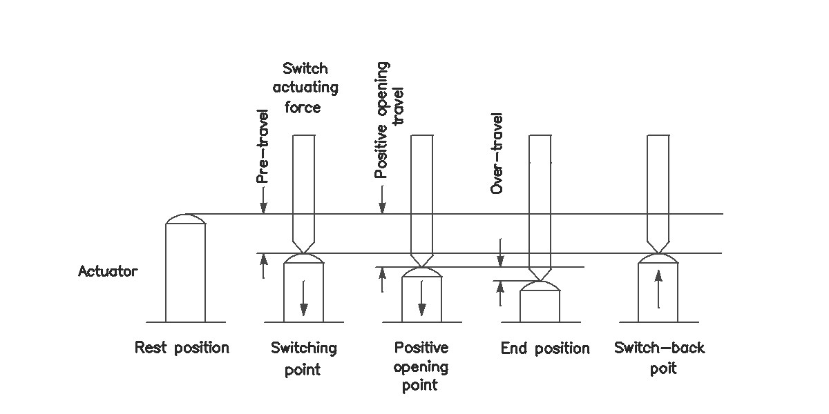
The switching actuating force is the force required on the actuator to move it from the rest position to the switching point.
The SK series includes sub-miniature switches with plastic actuators.
In contrast to the snap-action switch, the slow action switch has no defined positions. The contact bridge moves simultaneously with the pedal. The faster the pedal is pressed, the faster the contact opens or closes.
The disadvantage of the slow action switch is that there can also be an undefined state.
Example: If the pedal is pressed slowly, the contact bridge moves away from the NC contact and this opens. At the same time, however, the NO contact is not yet reached and so there is a dead center. The foot switch can also be held in this position.
Another disadvantage of this is that slowly approaching or removing the contacts can lead to arcing at higher power levels, which shortens the service life of the contacts.
The SM series includes sub-miniature switches with metal actuators.
Snap-action switches have two defined positions (open-closed).
When the switch is actuated, a plate inside the switch is pre-tensioned. When this plate reaches its switching point, the mechanical system of the switch snaps abruptly into the other switching position. This means that the switch is either open or closed.
There is no intermediate position.
ASA sub-miniature switches have been used with great success for many years in all areas of mechanical and plant engineering, particularly in control and automation technology. ASA sub-miniature switches are used as command devices wherever machine processes have to be queried, controlled, monitored or counted.
To be able to select the right switch for an application, the conditions under which the limit switch has to operate must first be determined, e.g. current to be switched, switching capacity, switching travel and actuating forces. Temperature ranges also play an important role. ASA sub-miniature switches are not only functional, they are precise and reliable and therefore offer a high level of safety. The high-quality materials used ensure a high level of design durability.
When developing this range of limit switches, particular emphasis was placed on the smallest possible, compact switch design and a space-saving arrangement of the switch components. This makes it possible to switch relatively high power levels in a very small space. A wide range of switch designs provides a high degree of flexibility. This not only makes the switches easier to use, but also allows individual problems to be solved.
There is a choice of switch inserts in several power ratings and switching systems, with gold-plated contacts or positive opening properties in accordance with DIN VDE 0113 Part 1 and DIN VDE 0660 Part 200. The IP65 protection rating in accordance with DIN 40050 allows use in extremely harsh environmental conditions. From simple standard switchgear to customer-specific special or individual solutions, the ASA range offers the right switchgear for every application.
Actuator positions
Rest position
The rest position of the actuator is the position in which no external force acts on the actuator.
Switching point / reset point
The switching point or reset point on the path of the actuator is the point at which the switching insert is activated or deactivated without any differential travel.
Forced opening point
The positive opening point on the path of the actuator is the point at which the positive opening of the contacts ends and the specified contact opening width is reached.
End position
The end position of the actuator is the position at the end of the mechanically permissible travel.
Travel of the actuator
Advance travel
The pre-travel distance of the actuator is the distance between the rest position and the switching point / reset point.
Overtravel
The overtravel distance of the actuator is the distance between the switching point and the end position.
Forced opening travel
The positive opening travel of the actuator is the minimum travel between the rest position and the positive open position of the switching elements of the NC contact with the contact opening width required by the relevant regulations.
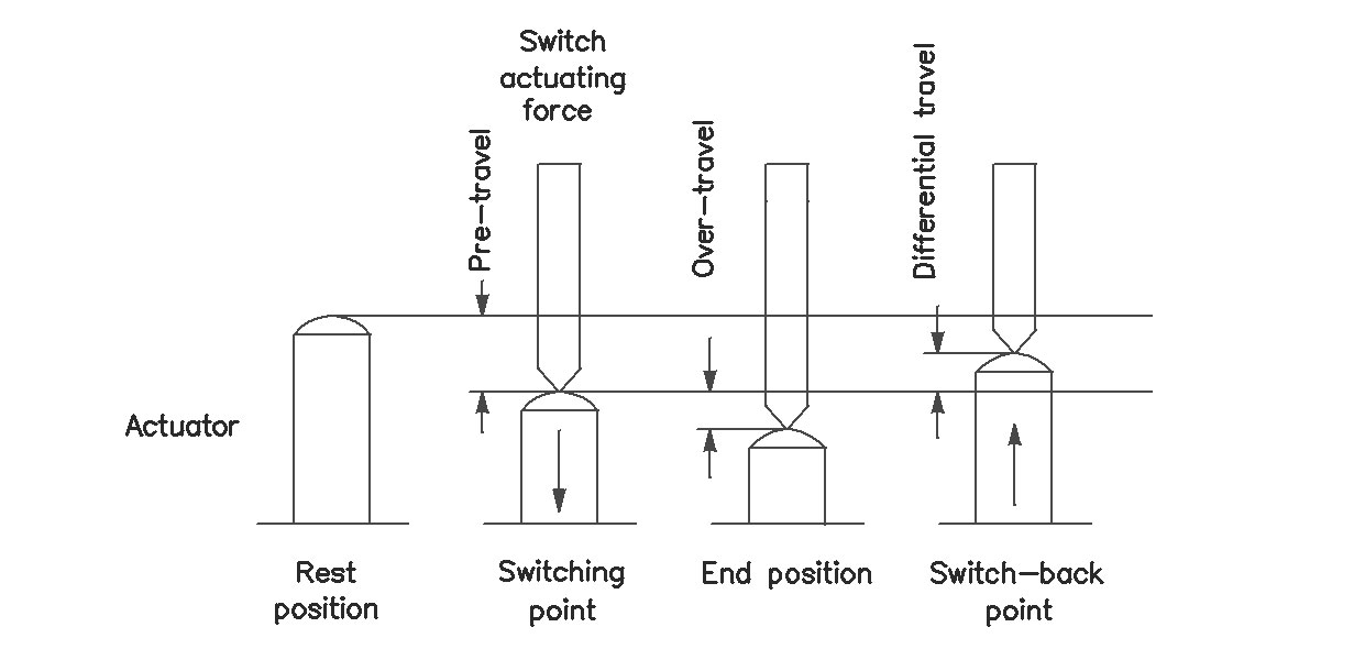
Actuator positions
Rest position
The rest position of the actuator is the position in which no external force acts on the actuator.
Switching point
The switching point on the path of the actuator is the point at which the switch insert is activated.
End position
The end position of the actuator is the position at the end of the mechanically permissible travel.
Switch-back point
The switch-back point on the travel of the actuator is the point at which the switching insert is returned to its initial position when the actuating force drops.
Travel of the actuator
Forward travel
The forward travel of the actuator is the distance between the rest position and the switching point.
Overtravel
The overtravel distance of the actuator is the distance between the switching point and the end position.
Differential travel
The differential travel of the actuator is the travel between the switching point and the reset point.
An additional transport bar can be used to conveniently position the foot controls on a machine. This eliminates the need to bend down or move the machine with your foot.
This very helpful accessory can also be retrofitted at a later date.
Have we sparked your curiosity?
Don't hesitate to contact us. We will advise you reliably and competently.